

There are two major misconceptions when it comes to Vector Network Analyzers (VNAs). One is they are very expensive. The other is they are very complicated to use. While historically, VNAs were extremely expensive, that's simply not the case today. With the advent of new technology, every RF engineer that uses a VNA can afford to have one on his or her workbench. In terms of ease-of-use, most measurements can be accomplished easily and accurately, using the factory calibration built into the VNA, or a very simple user calibration.

Let's first address the cost of VNAs. In the mid to late 1980s, a VNA could easily cost up to $100K – that's about what you would have paid for a house back then. Following the trend of most electronic devices, the average price of today's traditional benchtop VNA is much lower than in the 1980s, but are still expensive. This forces many companies to buy older VNAs off the used market and/or to have a limited number of VNAs that must be shared. And let's not forget the cost of the test port cables, adapters and calibration kit that will be needed. These add significantly to the total cost of the VNA solution. Plus, since the test port cables, adapters and calibration kit wear out, you cannot or should not buy these used.
Today there are other low-cost alternatives to the used market. Several manufacturers now offer modular or disaggregated VNAs. These disaggregated VNAs separate the core measurement engine of the VNA from the data processing and display portion, enabling use of a low-cost PC for the processing and display instead of a custom embedded controller. It also allows taking advantage of improvements in processing and networking capabilities by simply upgrading the PC without having to replace the core VNA engine. The disaggregated VNA solution is much smaller and more transportable, requiring less bench space and enables you to take the VNA to the DUT as opposed to bringing the DUT to the VNA. This is especially useful if you are measuring components in a large system or if you need to measure a DUT at a tuning or repair station.
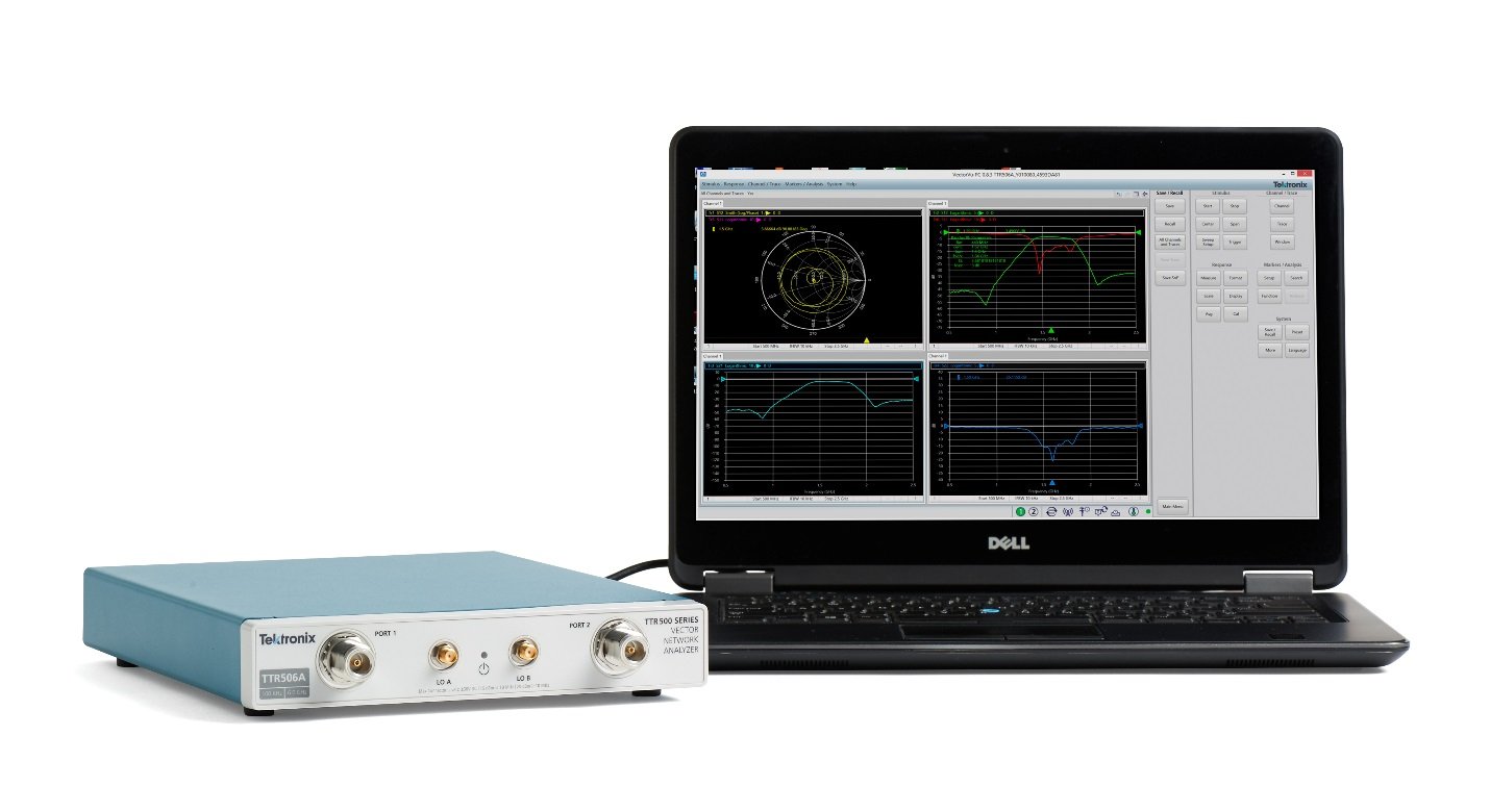
The Tektronix USB-based VNAs use this disaggregated approach. The TTR503A/TTR506A VNAs are low cost and small but have the accuracy and reliability of more expensive benchtop VNAs. They provide a very affordable total VNA measurement solution. And for our U.S. and Canadian end-users, Tektronix is running a limited time offer for a "Lite Edition" VNA with an even lower price, with up to a 6 GHz frequency range.

Now let's talk about reality and the complexity of effectively using a vector network analyzer. Many of you don't use a VNA every day and there are a lot of reasons you may not have wanted or been able to use a VNA as part of your typical test regime. Well, VNA measurements are not as complicated or challenging as you think – anymore.
You just want to verify the functionality of a design, trouble shoot a system, and determine if the unknown device in the lab drawer is a low pass filter or bandpass filter. These types of measurements don't require the ultimate in accuracy and are therefore very easy to make. With the built-in factory calibration, new VNA's can make accurate measurements right out of the box without further user calibration. Calibration has historically been one of the most difficult parts of making measurements on a VNA. The TTR503A/TTR506A come calibrated from the factory with return loss accuracy of >122 dB, at the test ports. This is more than accurate enough for most applications.
Of course, if you are measuring the transmission characteristics of a device, you will need to add at least one test port cable to the VNA. This cable will degrade the transmission accuracy of the factory calibration, primarily the phase. Or you may need to add adapters to the VNA test port to connect to your device. This adapter will degrade the return loss accuracy of the factory calibration, again mostly the phase. No need to fret. A simple one port response calibration or transmission response calibration can easily correct for the cables or adapters.
To perform a 1-port response calibration, it is best to use a precision open circuit standard or precision short circuit standard, but decent results can be made by just leaving the test port open.
Response calibration (Short/Open) – Reflection Test
- 1-port calibration
- Connect an Open or Short standard to a test port of the VNA to perform reflection test.
- Calibration eliminates the reflection tracking error from the network.


Procedure:
For the appropriate standard (short or open) that you want to calibrate,
- In the Cal > Calibrate menu, select Response calibration.
- Select the appropriate soft key for the standard (short or open).
- Select the test port to calibrate the standard. The dialog box for the port opens.
- Connect the standard from the calibration kit to the test port of the VNA. Make sure you select the right gender.
- Click the appropriate standard button in the dialog box of the port. The VNA records a trace measurement. When the measurement is complete, a check mark appears next to the standard button in the port dialog box.
- Click Apply to apply the calibration data. The VNA creates and saves calibration coefficients. The error correction function is also enabled.


Figure. S11 magnitude and phase measurements of bandpass filter with correction ON (yellow) and correction OFF (red), using a response calibration (short) on port 1.
A 2-port response calibration is just as easy, since no calibration standards are required. Just connect the test ports together using a phase-stable cable.
Response calibration (Thru) – Transmission Test
- 2-port calibration
- Connect a Thru standard (phase-stable cable, in this case) to each test port of the VNA to perform the transmission response calibration.
- Calibration eliminates the frequency response transmission tracking error from the network.


Procedure:
- In the Cal > Calibrate > Response menu, select the Thru standard.
- Select a Thru measurement:
- When the stimulus is at port 1 and you measure the response at port 2, you measure the S21 parameter.
- When the stimulus is at port 2 and you measure the response at port 1, you measure the S12 parameter.
- Connect the Thru standard (phase-stable cable, in this case) to both test ports of the VNA.
- Click the Thru standard button in the dialog box of the test port. The VNA records a trace measurement.
- For an optional isolation calibration, connect the Load standard to each of the test ports. Click Isolation to make the measurement.
- Click Apply to apply the calibration data. The VNA creates and saves the calibration coefficients. The error correction function is also enabled.


Figure. S21 magnitude and phase measurements of bandpass filter with correction ON (yellow) and correction OFF (red), using a response calibration (thru) from port 1 to port 2.
For a complete description of the various calibration methods and their associated trade-offs refer to the primer titled "Introduction to VNA Basics." That you can download here.
If you are familiar with using any of the common VNAs on the market today, it will be easy to transition to newer models, even though they may be disaggregated and the measurement application is running on an external PC, the user interface is very similar to the user interface of other popular benchtop VNAs. The Tektronix VNA application also has built-in context sensitive help and provides examples of some common measurements.
With the low total solution cost of the TTR503A, TTR506A, and TTR506A "Lite Edition" (including accessories), quality performance VNAs have never been more affordable. For information on the Tektronix VNAs and the limited time offer for the TTR506A, Lite Edition, please click here: https://www.tek.com/vna/ttr500